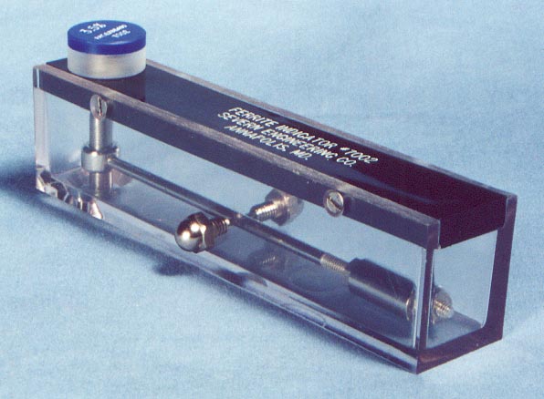
Ferrite Indicator

The Ferrite Indicator is a simple, rugged, non-destructive inspection instrument developed for laboratory, shop and field use. The GO, NO-GO feature permits instant acceptance testing of austenitic stainless weld metals. The Indicator requires no external standards, no adjustments, no visual readings and is unaffected by position. It performs equally well on sheets, plates, rods, irregular shaped objects and individual parts of complex components. It is effective in locating areas of high or low Ferrite content heterogeneous products.
Details
Description
Operation
The operation of the Indicator is based on the mutual attraction of a permanent bar magnet for a calibrated insert and an unknown material. In use, an insert is screwed into the top of the case. The magnet is then attracted to the insert by a force dependent upon the insert’s ferrite value. The end of the magnet projecting from the opening in the bottom of the case is then brought into contact with the material being tested. It is essential that the contact surface be clean and free from oxide scale or foreign material. The Indicator is then moved away in a direction perpendicular to the contact surface. If the material being tested has higher ferrite content than that of the calibrated insert, then the magnet will completely separate from the bottom of the insert as the Indicator is moved away. A complete separation occurs when the metal collar holding the magnet strikes the bottom of the plastic case. If the ferrite content of the material being tested is lower than that of the insert value, the magnet will first separate from the test material as the Indicator is moved away. Thus, by interchanging the inserts, it is possible to bracket the ferrite content of the materials under test.
The Ferrite Indicator is available with the following types of calibrations:
Type I – Percent Ferrite (%) system based on in-house Ferrite Standards developed by the Severn Engineering Co. and in continuous use since 1954.
Type II – The Ferrite Number (FN) system uses secondary standards traceable to the National Bureau of Standards through a set of coating thickness standards and conforms to all of the requirements of ANSI/AWS 4.2-2006. Type II Indicators come with an additional Check Insert as required by this specification.
Available Insert Values
The Indicator is available with any combination of inserts. Insert values available are:
| 0.5 | 1.0 | 1.5 | 2.0 |
| 2.5 | 3.5 | 5.0 | 7.5 |
| 10 | 12.5 | 15 | 17.5 |
| 20 | 22.5 | 25 |
Available either as % or FN.
Four inserts are included in the price of the Indicator. When ordering, please specify the Inserts desired. Additional Inserts may be added to the set. All Inserts are calibrated for a specific Indicator and a certificate of calibration is included with each Instrument. It is recommended that the Indicator be checked for accuracy and recalibrated yearly.
Instructions for Use
Download Instructions (pdf format)
